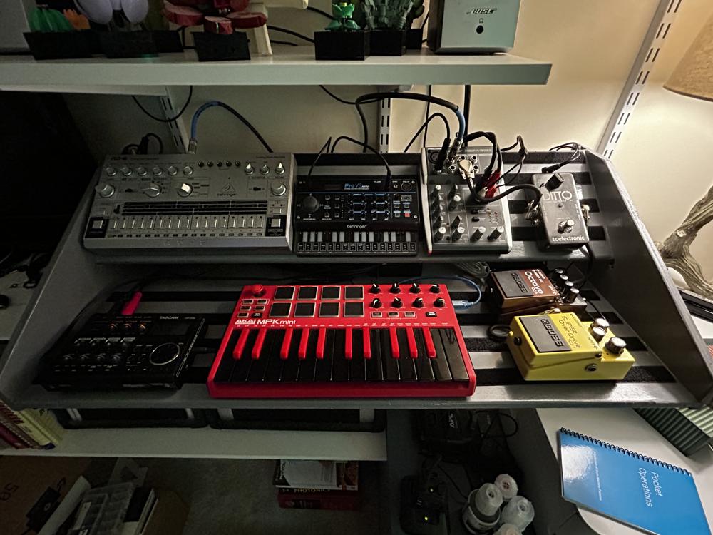
Mobile Synth Tray
Over the past month or two, I’ve been branching out into new musical adventures, and picked up a few new pieces of gear: A drum machine, synth module, mixer, MIDI keyboard, and digital recorder.
I needed a way to organize, power, and transport everything without having to break it all down between moves, so I came up with this mobile synth tray.
Requirements
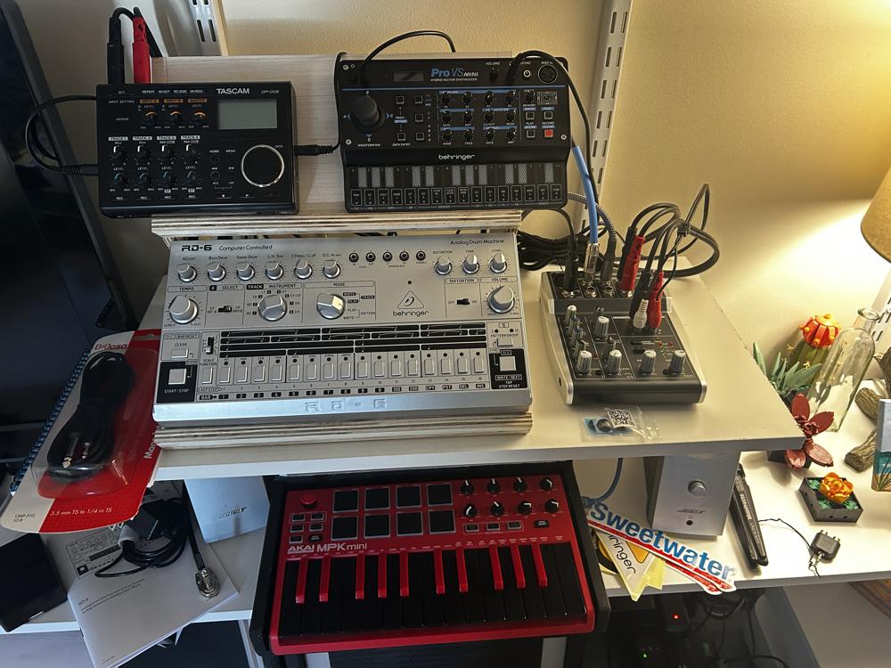
I wanted to build a two-tier tray with a flat section for the keyboard, and an angled upper shelf so I can easily see screens and access hardware controls. I also wanted it to be reconfigurable, but secure during transport. Inspired by a guitar pedal board, I figured Velcro was my best bet to make this work.
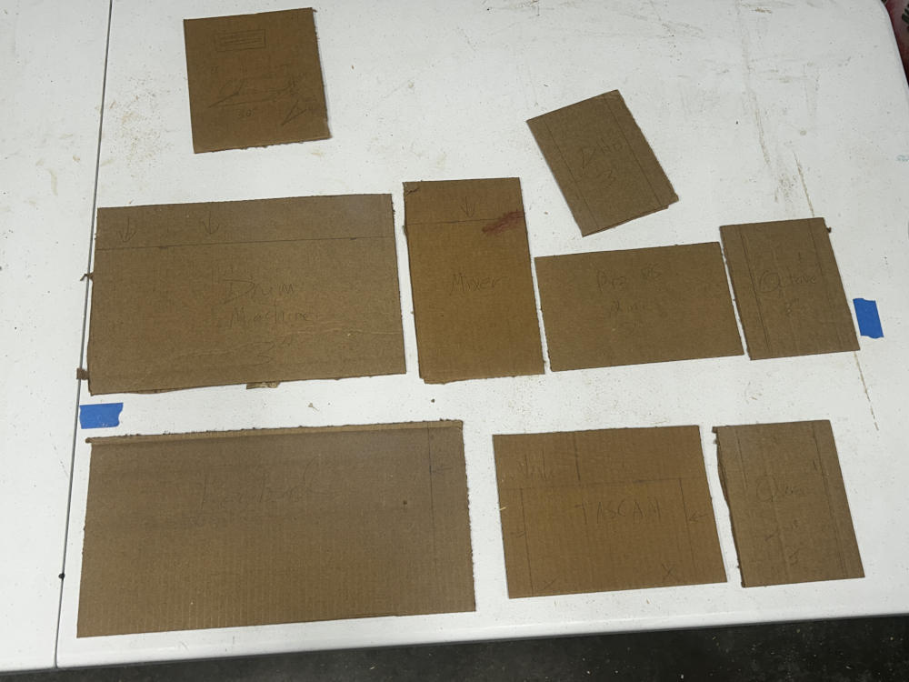
I started by tracing a rough outline of each piece of hardware on some scrap cardboad, including space for cables to be routed. I played around with the layout until I found the dimensions of each shelf, giving myself a little room for future equipment, but not too much room to send me on a shopping spree to fill the space.
| Part | Length | Depth |
|---|---|---|
| Each shelf | 31.5" | 8" |
| Overall | 32" | 16" |
Design
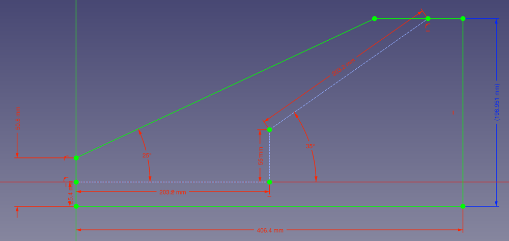
Using FreeCAD, I created the sketch above for the two side flaps, then extruded each shelf between them. The model below is a little crude, with no slots to fit the shelf into the flap, but I knew what I needed to do once I started the woodworking.
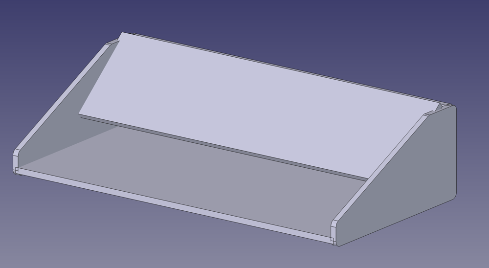
This is the first large project I designed in FreeCAD, which is proving to be a contender in the CAD space since it’s 1.0 release.
Assembly and Painting
I started with a 2’x4’ piece of 1/2" plywood, broke it down with a circular saw, then used my radial arm saw to cut the angle in each each flap. Using a palm router, I cut slots in the flaps for dado joints, then assembled the tray with wood glue and brad nails.
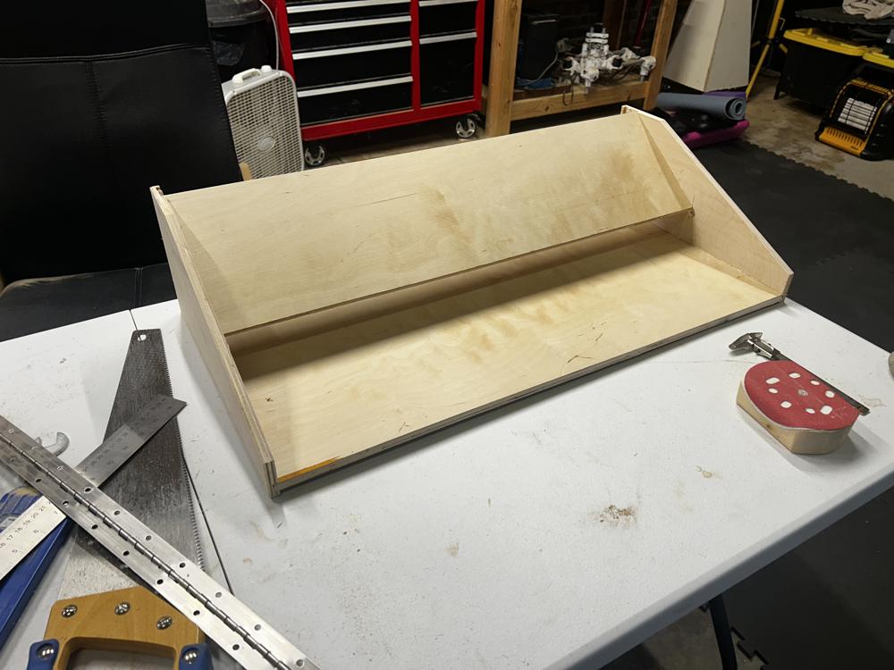
Using a 1/4" roundover bit in the router, I smoothed the edges of the shelves so cables and hands would not be damaged by sharp corners. All other edges were knocked down with a couple passes from a random orbital sander.
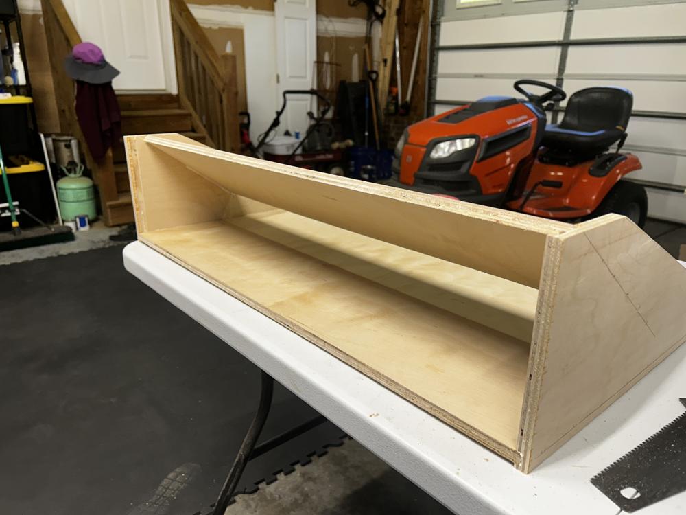
Once assembled, I routed out a hole in the side for the power plug and switch, then painted with an oil-based protective enamel. The color is smoke gray, with a glossy finish so the velcro has a smooth surface to adhere to.
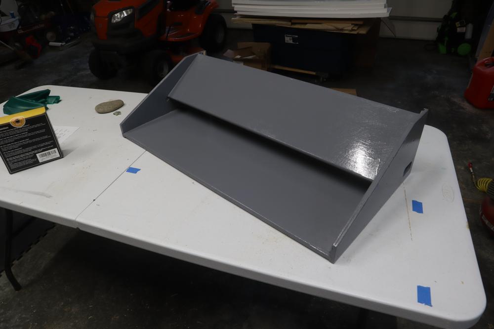
I cut the end off a 6-outlet power strip, then soldered the wires to blade connectors that are then fit onto the switch/jack.
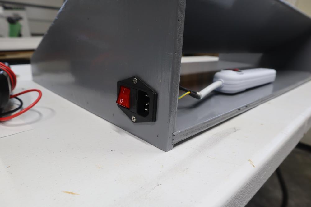
To cover up the back, there is a 1/2" plywood panel that can be slid into place, keeping the power and cables contained underneat the upper tier of the tray.
Layout
I picked up about 16 feet of velcro with an adhesive back, and placed the “loop” strips along the length of the board, each spaced about 1 inch apart.
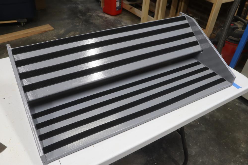
I then cut strips of the complementary “hook” adhesive, and and attached it to the bottom of all my new gear. This allowed for easy repositioning of the gear to the board.